
An automatic L-bar sealer relies on coordinated film handling, product conveying, sealing motion and sensor signals. When an alarm stops the machine, the message identifies where to begin checking. It does not always identify the component that needs replacing.
This guide is based on troubleshooting experience from the equipment manufacturer’s engineering team for our TY-6050 L-bar sealer. It covers emergency stop, sealing blade switch, film unwinding, film rewinding, guard door, waste film, sealing parameter, anti-cut protection and servo drive alarms.
Use it to understand the symptoms, identify the relevant checks and prepare useful information for technical support. Control labels, sensor arrangements and parameter settings vary between machines. Follow the instructions supplied for your specific equipment.
Download Troubleshooting Guide (PDF)
The downloadable guide brings together reference photos, control-screen examples and troubleshooting notes for use alongside your machine documentation.
Before You Start
Read and record the exact alarm message before changing any settings. Note whether the alarm appeared during start-up, after a film change, during product feeding or while the sealing jaw was moving.
Keep hands clear of the sealing jaw, rollers, conveyors and moving mechanisms. Isolate electrical power and other hazardous energy sources according to the machine’s maintenance procedure before clearing entangled film, opening electrical enclosures or inspecting mechanical connections. Sealing components may remain hot after the machine stops.
Electrical diagnosis, powered sensor testing and adjustments to protective devices must be handled by qualified personnel using the manufacturer’s procedure. Do not bypass safety interlocks or reduce protection sensitivity to keep production running.
Common Alarms at a Glance
| Alarm or symptom | Where to begin |
|---|---|
| Emergency stop alarm | Check whether the E-stop is released; if the alarm remains, investigate its input signal and circuit. |
| Sealing blade switch alarm | Check the selector position and the corresponding input signal. |
| Film unwinding alarm | Check film loading, roller entanglement, unwind demand and sensor response. |
| Film rewinding alarm | Check for broken film, speed mismatch and abnormal sensor response. |
| Guard door alarm | Check that the guard is correctly closed; have its detection circuit checked if necessary. |
| Waste film overflow alarm | Check whether the collection roll is full or the alarm occurs prematurely. |
| Sealing parameter alarm | Review the opening and stroke settings for the specific control system. |
| Anti-cut protection alarm | Check product clearance, product alignment and the protective mechanism. |
| Servo drive alarm | Record the drive fault code, then investigate mechanical resistance and cable connections. |
1. Emergency Stop and Sealing Blade Switch Alarms
Emergency Stop Alarm
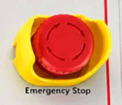
The engineering guide identifies two possible causes: the emergency stop button remains pressed, or the E-stop circuit is open because of a loose, disconnected or damaged wire.
First, confirm that the reason for the emergency stop has been resolved. On the rotary-release button shown in the guide, turn the red button clockwise until it releases. Follow the markings on your own machine if its button differs.
If the alarm remains, a technician should check the E-stop status on the machine’s I/O screen. An abnormal signal requires inspection of the circuit between the button and the PLC, including the wiring and the contact block behind the button.
Sealing Blade Switch Alarm
On the selector shown in the guide, the left position is OFF and the right position is ON. Check the machine’s markings and operating procedure before changing its position.
If the correct selector position does not clear the alarm, the next checks are the input signal, the wiring between the switch and PLC, and the switch contact block.

2. Film Unwinding Alarms
Film unwinding problems can originate in film loading, an imbalance between feeding and unwinding speeds, an abnormal sensor signal or a drive fault.
Check Film Loading After a Roll Change
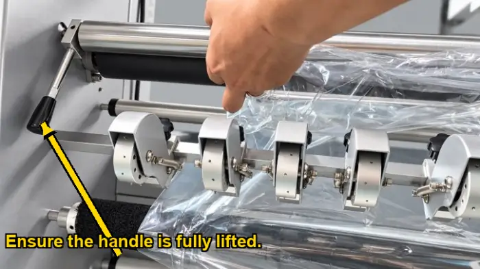
On the assembly shown in the engineering guide, the roller handle must be fully lifted after loading so the rollers clamp the film correctly. An incorrectly positioned handle can leave the film without the required tension.
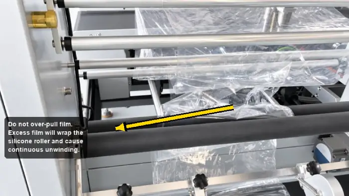
Excessive film pulled out during pre-feeding can also wrap around the silicone roller. This may cause continuous unwinding and an alarm. Stop and isolate the machine before removing entangled film.
Review Feeding and Unwinding Speeds
If film feeding is faster than the unwind system can supply, the unwind system cannot keep up with demand. Have a trained technician review the relevant settings together, including film feeding, unwinding and rear conveyor speed where applicable.
Avoid changing several parameters at once. Record the existing values so each adjustment can be evaluated.
Check Sensor and Drive Signals
The documented unwind system uses a sensor signal to initiate film supply. If the mechanism moves but the sensor does not register the expected condition, the PLC may not command the unwind motor.
A technician should compare the physical mechanism position with the sensor signal. Drive wiring and the RS-485 communication connection are further checks when a drive or communication fault is indicated.
3. Film Rewinding Alarms
Possible causes documented by the engineering team include a mismatch between rewinding and feeding speeds, a continuously active sensor, broken film and a stalled motor.
Begin by checking whether the film is intact and whether the collection mechanism moves as expected. If film repeatedly breaks, review film condition and the rewinding settings with technical support.
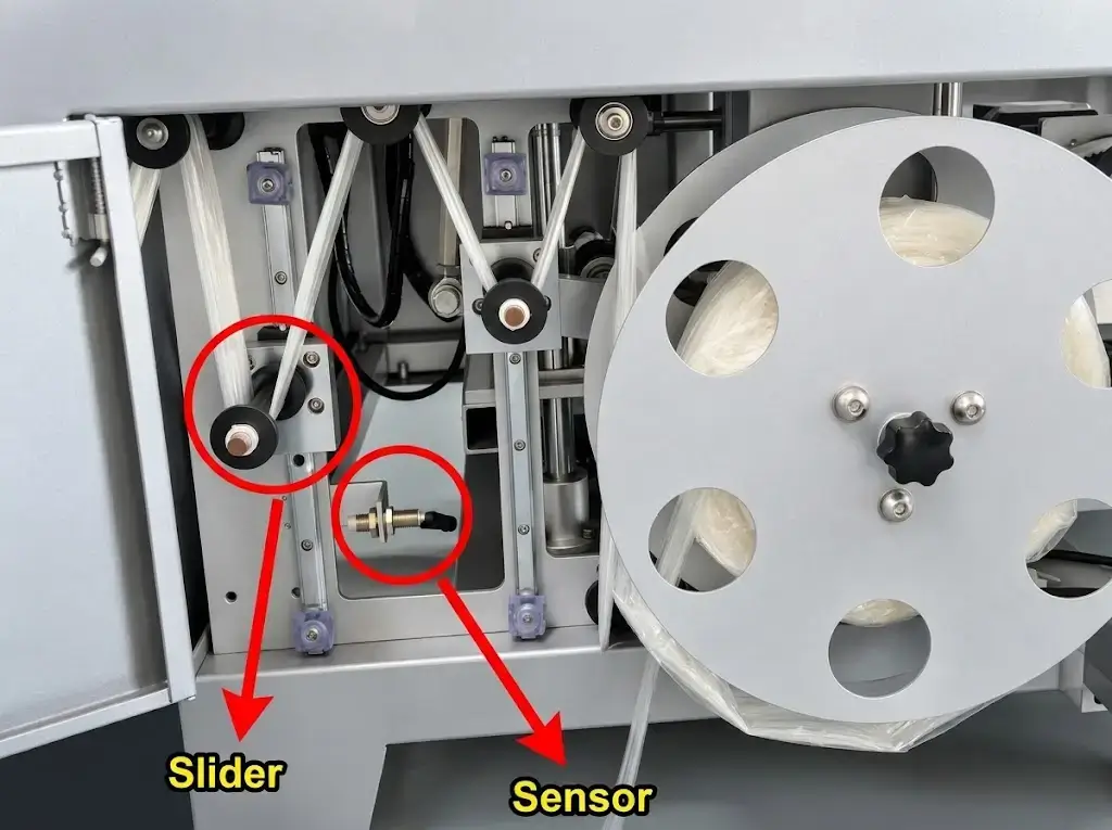
In the slider-and-sensor arrangement shown in the guide, film tension changes the slider position, which changes the sensor signal used to control rewinding. Broken film can leave the slider in a position that continuously requests rewinding.
If the sensor remains active when the slider should have moved clear, a technician should inspect the sensor, its mounting and its wiring before deciding whether replacement is necessary.
4. Safety Guard Door Alarms
A guard door alarm can occur when the control system does not receive the expected guard-detection signal.
Check that the guard is correctly closed. If the alarm persists, a qualified technician should inspect the detector arrangement and its circuit using the machine’s approved procedure.
The engineering guide identifies sensor response, wiring condition and detection distance as areas to investigate. Do not operate the machine with the guard detection bypassed.
5. Waste Film Overflow Alarms
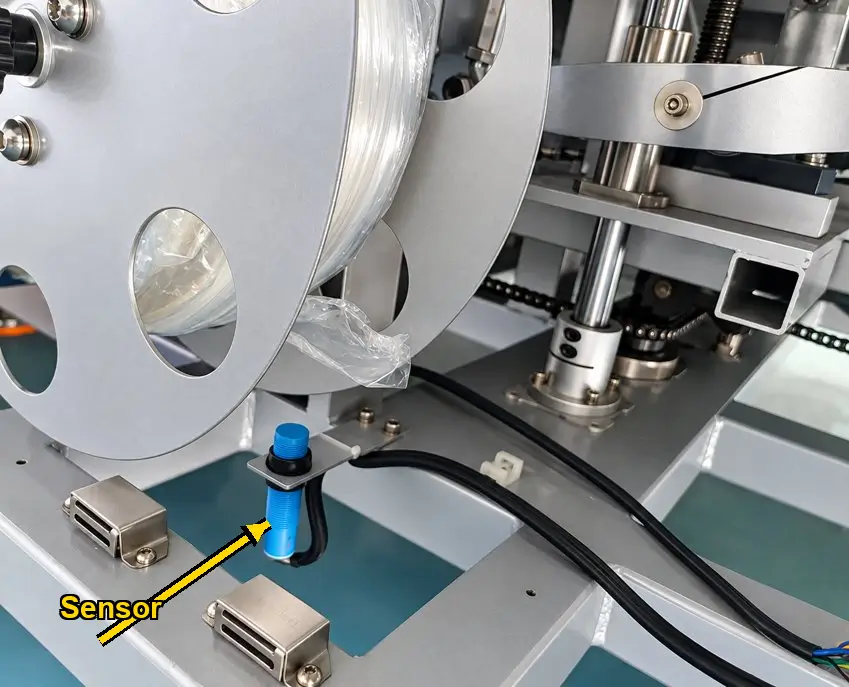
The documented waste film collection system uses a proximity sensor to detect when the accumulated roll reaches the sensing area.
A full collection roll: Stop the machine and remove the accumulated waste film according to the machine’s procedure.
An alarm when the roll is barely filled: Have a technician check the sensor mounting position and detection clearance. The guide identifies incorrect positioning as a possible cause of premature detection.
An indicator that does not respond as expected: Have the sensor and its circuit checked. An abnormal indicator alone is not enough to confirm which component needs replacing.
Distinguishing these conditions helps separate routine waste removal from a detection fault.
6. Sealing Parameter Alarms
The control screen shown in the engineering guide includes parameters labelled Blade Opening and Blade Stroke. These settings relate to the sealing jaw’s opening and closing positions.
If a sealing parameter alarm appears, record the exact message and the current values. Ask technical support to confirm the permitted relationship between the settings for your machine and control version.
Do not transfer parameter values from another machine or assume that a displayed value has the same meaning across different control systems.
7. Anti-Cut Protection Alarms
The engineering guide describes two situations that can trigger protection:
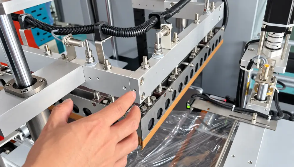
- A product remains beneath the sealing jaw or has not cleared the vertical photoelectric detection zone.
- The sealing blade guard contacts a product and activates the protective trigger mechanism.
Begin by checking product clearance and alignment. Film tension can shift or rotate a product during feeding, leaving part of it within the detection zone.
Technical support may need to review the rear seal margin, feeding and conveying speeds, and infeed guide rail arrangement for the application. Any change to the protective trigger block or sensor position requires the manufacturer’s procedure and verification of the protection function.
8. Servo Drive Alarms
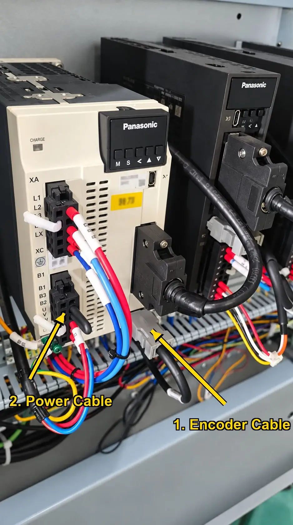
The engineering guide identifies mechanical resistance and loose encoder or power connections as possible causes of servo alarms.
Record the fault code shown on the drive before restarting or changing anything. Under the machine’s approved isolation procedure, a qualified technician can inspect the gearbox, chains, gears and mechanical connections for obstruction or looseness.
The encoder and motor power cable connections should also be checked at both the drive and motor ends.
If the alarm remains, send the fault code and the completed checks to technical support. A persistent alarm does not, by itself, prove that the servo drive needs replacing.
What to Send When You Request Technical Support
To help the technician understand the problem, provide:
- The machine model and serial number.
- A photo of the complete alarm message and any drive fault code.
- The operating stage at which the alarm appears.
- Relevant parameter-screen photos, including values before any changes.
- A description of recent film, product or setting changes.
- A short video taken from a safe position with guards in place, if requested.
- The checks already completed and their results.
Download the Illustrated Troubleshooting Guide
For reference photos, control-screen examples and the engineering team’s troubleshooting notes, download the companion guide and keep it with your machine documentation.
Download Troubleshooting Guide (PDF)
For machine-specific help, contact us with the alarm message, machine details and the checks already completed.